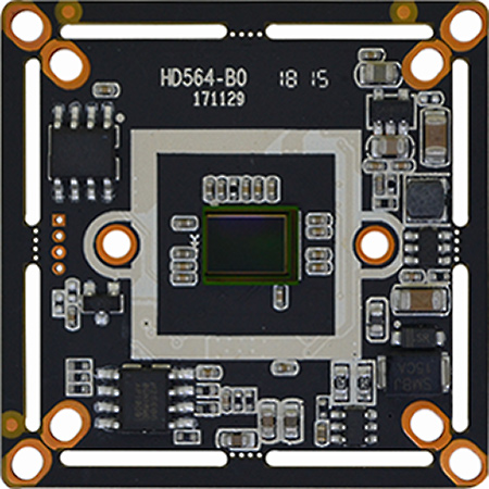
1/2.7" SOI K02 4MP FH8538M AHD TVI CVI Analog 4 in 1 CCTV security Camera board
$9.20
Availability:
In stock
Out of stock
Variations
Product Description
Technical Characteristics:
SOI K03 5MP HD image sensor, with high definition 5MP AHD/TVI; 4MPCVI; CVBS 960H output, effective resolution is up to 2704H * 1950V
OSD menu supports 2 different languages with white balance, mirror, digital noise reduction function
Adopt Fulhan FH8538M DSP, with OSD function (color / white-black, PAL / NTSC)
Support dual filters switch, day-night effect is distinct, various day-night modes can be switched by OSD menu
Support UTC, mirror, flip
Power (600W) Video (2KV) dual-lightning protection design, OSP antioxidant PCB, size 32 * 38 dual-border.
| Product parameters | |
| Image Sensor | 1/2.5" SOI K03 |
| Effective Pixels | 2704(H) * 1950(V) |
| Effective resolution | 5MP |
| Signal system | PAL/NTSC (Switched by OSD) |
| Day-night mode | External control(default) / Auto / Color / White & black (OSD switch) |
| S/N ratio | ≥50dB |
| Minimum illuminaiton | 0.2LUX |
| BLC | AUTO |
| (AES) Auto electronic shutter | AUTO / 1/50(1/60)-1/50,000sec |
| (AWB)Auto white balance | AUTO |
| IR control voltage input | OFF(DC 0V) / ON(DC 3-8V) |
| OSD language | English/ Simplified Chinese |
| Video output | AHD/TVI/CVI/CVBS |
| Video record occupation | 1minute about 35.2MB (3.6mm lens) |
| Power consumption | DC12V / 69mA ± 6mA (wide voltage 9V-18V) |
| Working temperature | -30°C to 70°C |

OSD Function description :
There're two methods to switch AHD / CVBS, OSD switching or [AHD / CVBS] pin short to GND switching, The default is OSD switching, short circuit to ground switching is in non-functional status.
When Burning A / C program, [AHD / CVBS] pin short circuit to GND, the output the output is analog CVBS. When burning this grogram, OSD shortcut switch function is non-functional.
In product wiring diagram, when [AHD / CVBS] pin is without any connection, the output is defaulted AHD.
OSD switching and [AHD / CVBS] pin short-circuit switching are two different programs, they can not be used in the same time.
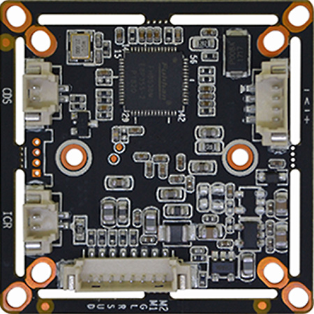
Pin definition:
OSD Menu Port
D Down (Orange)
U Up (Gray)
E Enter (Purple)
R Right (Green)
L Left (White)
G GND (Brown)
M1 M2 Can set to Mode switch or Alarm Output
Power video port
V Yellow
-/G Ground
+ Power+
CDS LED board photoresist
ICR IR-CUT dual filter switch