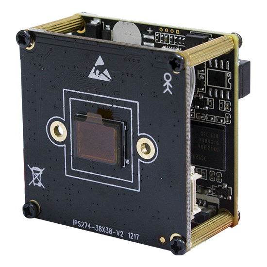
1/2.5" 8MP IMX274 Hisilicon Hi3519V101 security CCTV IP Camera board H.265 H.264
$127.00
Availability:
In stock
Out of stock
Variations
Product Attributes
Product Description
1/2.5" 4K 8MP CMOS image sensor;
Support H.265/H.264/MJPEG
Support three stream, Main-stream: 3840*2160;sub-stream:704*576/640*360/352*288
Support WDR, 3D-NR, HLC, BLC, Auto-White balance for different environment
Support ONVIF;Can connect with other company's NVR
ICR switching to surveille 24 hours
Support image shutter, 4 shutter area can be set
Support audio input/output
Support motion detection, motion detection alarm will be send to email automatically
Support OSD setting and network timing
Support mobile surveillance(iOS, android), Web and VMS;
Suport PoE (optional);
| Main chipset | Hi3519V101 |
| Image sensor | 1/2.5" 8MP Sony IMX274 |
| Features | |
| D/N | Support D/N switching (support IR-CUT) |
| Shutter | 1/12-1/10000 |
| White balance | Auto |
| BLC | Support |
| Noise reduction | 3D-NR |
| WDR | D-WDR |
| Motion detection | Support |
| Privacy region | 4 areas |
| Mirror | Support |
| OSD | Support OSD setting, drag the position freely |
| Scheduled Reboot | Support |
| Video | |
| Compression | H.264, H.265, MJPEG |
| Resolution | |
| Main-stream: | 3840*2160 |
| Sub-stream: | 704 * 576 / 640 * 360 / 352 * 288 |
| Frame rate | 25fps(50Hz), 30fps(60Hz) |
| Bit rate | 64Kbps~16Mbps CBR / VBR adjustable |
| Video adjustments | Brightness, saturation, hue, contrast, sharpness |
| Network | |
| Ethernet | RJ-45 10M/100M |
| WiFi | Not available |
| Network protocol | HTTP, TCP/IP, IPv4, UPNP, RTSP, UDP, SMTP, NTP, DHCP, DNS, IP Filter, DDNS, FTP, IP Search (Support P6S IP camera, DVR, NVS etc.) |
| Access protocol | Support ONVIF 2.4 / privacy protocol / CGI |
| Max users | 8 |
| Client | iPhone, iPad, Android, Windows |
| Audio | |
| Audio | G.711U G.711A |
| Input | 1ch Input |
| Output | 1ch Output |
| General specifications | |
| Size | (38x38) |
| Temperature | -30℃~+60℃ |
| Power | DC12V 2A |
 |  |
 |  |
| JP1 Power interface | Preview | Pitch | |
| 1 | DC12V |  | 1.25mm |
| 2 | Video GND | ||
| 3 | CVBS output | ||
| 4 | GND | ||
| JE1 Network interface |
| 1.25mm | |
| 1 | RJ45_1 (TX+) | ||
| 2 | RJ45_2 (TX-) | ||
| 3 | RJ45_3 (RX+) | ||
| 4 | RJ45_6 (RX-) | ||
| 5 | Network connection indicator light (green light) | ||
| 6 | Network status indicator light (yellow light) | ||
| Sensor board J1 IR-cut interface | 1.25mm | ||
| 1 | IR-CUT control signal 5V- | ||
| 2 | IR-CUT control signal 5V+ | ||
| Sensor board J2 DC auto Iris interface (Support automatic aperture model: -AI) | 1.25mm | ||
| 1 | drive- | Depend on color definition of Lens | |
| 2 | damp- | ||
| 3 | drive+ | ||
| 4 | damp+ | ||
| Sensor board J3 Power Auto Zoom lens interface (Support Electric lens model:-AZ) | 1.25mm | ||
| 1 | Focus A- | Depend on color definition of Lens | |
| 2 | Focus A+ | ||
| 3 | Zoom A- | ||
| 4 | Zoom A+ | ||
| 5 | Zoom B+ | ||
| 6 | Zoom B- | ||
| 7 | Focus B- | ||
| 8 | Focus B+ | ||
| Sensor board J4 No definition | |||
| J5 Infrared Light board interface | 1.25mm | ||
| 1 | Infrared Light board12V power output | ||
| 2 | GND | ||
| 3 | LED feedback signal input(0.8V-12V) | ||
| 4 | Infrared Light enable control | ||
| J6 function interface | 1.25mm | ||
| 1 | Audio in | Support powerless microphone and Line in | |
| 2 | Audio GND | ||
| 3 | Audio out | ||
| 4 | GND | ||
| 5 | Reset | ||
| 6 | Alarm in 1, low level effective | ||
| 7 | Alarm in 2 (reserve), low level effective | ||
| 8 | Alarm out control GPO, 3.3V level signal | ||
| 9 | RS_485+ | ||
| 10 | RS_485- | ||
| JU1 USB interface | 1.25mm | ||
| 1 | GND | Support MT7601 / RT5370 USB wifi module. | |
| 2 | USB_DP | ||
| 3 | USB_DM | ||
| 4 | 5V power out | ||
| J7 expandion board | FPC | ||
| 1 | USB_DP | ||
| 2 | USB_DM | ||
| 3 | System | ||
| 4 | SDIO Work Clock | ||
| 5 | SDIO Data3 | ||
| 6 | SDIO Data2 | ||
| 7 | SDIO Data1 | ||
| 8 | SDIO Data 0 | ||
| 9 | System | ||
| 10 | SDIO Order | ||
| 11 | SDIO Power enable control signal | ||
| 12 | SDIO Card detection signal | ||
| 13 | SDIO Pull-up resistor power out | ||
| 14 | Alarm out control GPO | ||
| 15 | System | ||
| 16 | DC5V Power out | ||
